UML Class Diagram - Level 5 #
1. Introduction#
When designing a system, before you start to implement a bunch of classes, you need to have a conceptual understanding of the system that you will be creating. They're a static representation of your system structure. As the basis of this was covered in the Level 4 documentation, this time we will mainly focus on the technical details, such as higher level relationships, rather than of the structure. If you need a refresher or aren't sure on the basics at this time, revisit the Level 4 document on Design.
2. Table of Contents#
- 1. Introduction
- 2. Table of Contents
- 3. UML Class Diagrams
- 3.1. The Technical Details
- 3.2 Class Visibility
- 3.3. Relationships
- 3.4. Association
- 3.5. Inheritance
- 3.6. Dependency
- 3.7. Aggregation
- 3.7. Composition
- 3.8. Realization
- 3.9. Cardinality
- 3.10. GUI Class Diagram Example
- 4. References
3. UML Class Diagrams#
3.1. The Technical Details#
We represent classes in a Class Diagram as a box with three compartments. The uppermost is the class name, the middle section contains the class attributes, and the bottom section contains the class methods.
The convention is.
- attribute name: type
- method name: (parameter:type)
Remember it is possible to set defaults if you want to.
3.2 Class Visibility#
Class members (attributes and methods) have a specific visibility assigned to them. See figure 3 below for more details on these.
| Class Visibility | Icon | Who Can See It? |
|---|---|---|
public |
+ | anywhere in the program and may bbe called by any object within the system |
private |
- | the class that defines it |
protected |
# | (a) the class that defines it or (b) a subclass of that class |
package |
~ | instances of other classes within the same package |
| Figure 1: Table representing the Visibility of Class members |
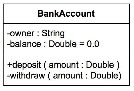
Figure 2: A Class represented in UML
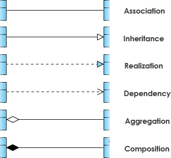
3.3. Relationships#
There are many different relationships that you can define within your class diagrams. These are;
- Association
- Inheritance
- Dependency
- Aggregation
- Composition
- Realization
3.4. Association#
This is a broad term that simply emcompasses just about any logical connection or relationship between classes. We represent Association as a simple straight line between two different classes. It is typical to name our associations using a verb or verb phrase which reflects the real world problem domain. Alongsaide typical Association, There are a couple of other types of Association that can be used, which are;
- Directed Association
- A directional relationship represented by a line with an arrowhead, where the arrowhead depcicts a container-contained directional flow
- Reflexive Association
- This occurs when a class may have multiple functions or responsibilities
3.5. Inheritance#
This refers to a type of relationship wherein one associated class is a child of another by virtue of assuming the same functionalities of the parent class. The child is a specific type of the parent class and inherits properties from that parent it is inheriting from. A solid line is used to represent Inheritance with an unfilled arrowhead.
3.6. Dependency#
An object of one class might use an object from another class in the code the method. If the object is not stored in any field, then this is considered, and modeled as a dependency relationship. This is a special type of association, similar to reflexive association, that exists between two classes if making changes to one of the classes will cause changes to another. The first class simply depends on the other class.
3.7. Aggregation#
This refers to the formation of a particular class as a result of one class being aggregated or built as a collection. In aggregation, the contianed classes are not strongly dependent on the lifecycle of the container. To show aggregation a diagram, draw a line from the parent class to the child class with a diamond shape near the parent class.
3.7. Composition#
This is quite similar to aggregation, with the only difference being its key purpose of emphasizing the dependence of the contained class to the lifecycle of the container class. The contained class will be obliterated when the container class is destroyed. To show compsotion on a diagram, use a directional line connecting the two classes, with a filled diamond shape adjacent to the container class and the directional arrow to the contained class.
3.8. Realization#
This denotes the implementation of the functionality defined in one class by another class. To show the relationship in UML, a broken line with an unfilled solid arrow is drawn from the class that defines the functionality of the class that implements the function.
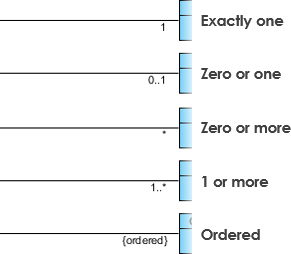
3.9. Cardinality#
Cardinality was touched upon in the Level 4 document in the Entity Relationship section. It is what refers to the expression in terms of one to one, one to many and many to many.
3.10. GUI Class Diagram Example#
The following example gives a taste of what a class diagram looks like for a GUI system. This diagram highlights all of the key relationships needed and has labels to help you indicate where the correct relationship needs to be used.
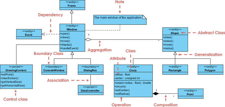
Figure 3: A Class Diagram representation of a GUI system
4. References#
[1] Creatly UML Class Diagrams Explained wih Examples https://creately.com/blog/diagrams/class-diagram-relationships/
[2] Visual Paradigm UML Class Diagram Tutorial https://www.visual-paradigm.com/guide/uml-unified-modeling-language/uml-class-diagram-tutorial/