Entity Relationship Diagram - Level 6 #
1. Introduction#
This section goes more into some more advanced notations that you can take advantage of in your ER Diagrams, which will allow you to model most of the interactions that will take place in a common system, but also model some more complex interactions if you want to.
2. Table of Contents#
3. Data Models#
There are three types of conceptual models when we think about ERDs. They differ in the purposes they are created for and for the audiences they are intended for. At university, you will likely only encounter the Physical Model, but it is useful at Level 6 to know about the other two types: the Conceptual Model and the Logical Model. You can find more in depth information about these models at [1].
3.1 Physical Model#
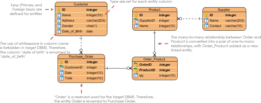
The physical model represents the actual design of a relational database. A physical data model elaborates on the logical data model by assigning each column with type, length, nullable etc. Since this kind of model represents how data should be structured and related in a specific DBMS (DataBase Management System), it is importnat to consider the convention and restriction of the actual database system in which the database will be created. It is important to make sure that the column types are supported by your DBMS and reserved words are not used in naming entities and columms.

Figure 1: Physical Data Model example
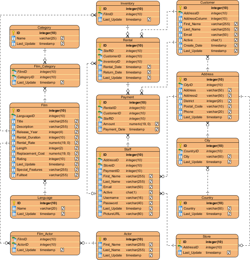
Below is another, more detailed example of a physical model showing a movie rental system:

Figure 2: ERD Example - Movie Rental System
3.2 Conceptual Model#
Conceptual ERD models the business objects that should exist in a system and the relationships between them. This type of model is developed to present an overview of the entire system by recognizing the business objects involved as well. It defines what entities exist, NOT which tables. A many to many table may exist in a logical or physical model, but they are just shown as a relationship with no cardinality in the conceptional model.
An example of a conceptual data model can be seen below:

Figure 3: Conceptual Data Model example
One interesting feature of the conceptual model is that it is the only data model that supports generalization. This is because it is used to model a 'kind of' relationship, such as a triangle being a kind of shape. This is the only model that can do this.
3.3 Logical Model#
Logical ERD is essentially just a detailed version of a Conceptual ERD. It is developed to enrich a conceptual model by defining explicitly the columns in each entity and introducing operational and transactional entities. The main difference between transactional data and operational data is that transactional data is the data that describes business events of the organization while operational data is the data that is used to manage the information and technology assets of the organization (reference [2]).
An example of a logical data model can be seen below:

Figure 4: Logical Data Model example
4. References#
- [1] Visual Paradigm: What is Entity Relationship Diagram https://www.visual-paradigm.com/guide/data-modeling/what-is-entity-relationship-diagram/#:~:text=Entity%20Relationship%20Diagram%2C%20also%20known,inter%2Drelationships%20among%20these%20entities
- [2] PEDIAA: What is the Difference Between Transactional Data and Operational Datahttps://pediaa.com/what-is-the-difference-between-transactional-data-and-operational-data