Sequence Diagram - Level 5 #
1. Introduction#
Following on from the level 4 document discussing the Sequence Diagram, which can be found here, we will look more into some higher level benefits of the sequence diagram and how these should be created. Remember that a sequence diagram is a type of interaction diagram that describes how (and in what order) a group of objects work together.
The main purpose of a sequence diagram, is to define event sequences that result in some desired outcome. The focus is less on messages themselves and more on the order in which messages occur. The diagram conveys this information along the horizontal and vertical dimensions, where the vertical dimension shows, top down, the time sequence of messages/calls as they occur, and the horizontal dimension shows, left to right, the object instances that the messages are sent to.
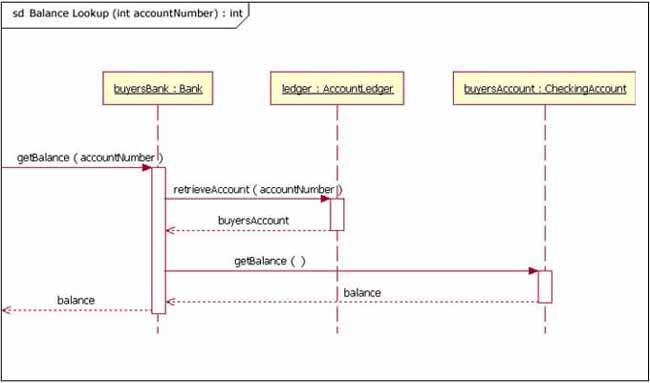
Figure 8: example Sequence Diagram
Notice in figure 8 that that the diagram starts with 'sd' which is normally used to indicate that this is a sequence diagram.
2. Table of Contents#
3. Sequence Diagram Basic Notation#
This section will go into more detail over different notations for a Sequence Diagram. Please refer back to Level 4 for the basic notations mentioned earlier, as not all the same notations are discussed here.
3.1. Frame#
In UML 2, the frame is an element that is used as a basis for many other diagram elements in UML 2, but the first place most people will encounter a frame element is as the graphical boundary of a diagram. In addition to providing the visual border, the frame element also has an important functional use in diagrams that depict interaction, such as the sequence diagram. Incoming and outgoing messages can make use of the frame, seen in figure 8 above, which is done by connecting the messages to the border of the frame.
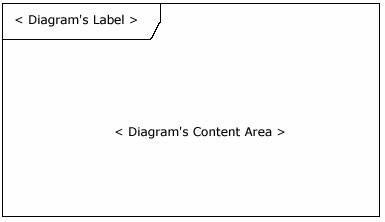
Figure 9: the Frame
3.2. Lifelines#
A lifeline represents an individual participant in the interaction. Lifeline notation elements are placed across the top of the diagram. They represent either roles or object instances that participate in the sequence being modeled. Lifelines are drawn with a dashed line descending from the centre of the bottom edge. The name of the lifeline is placed inside the box.
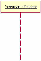
Figure 10: the Lifeline
The lifeline in figure 10 represents an instance of the class Student, whose instance name is freshman. The lifeline name here is underlined, which means that the lifeline represents a specific instance of a class in a sequence diagram, and not a particular kind of instance (a role). Sequence diagrams can include roles, even if they don't really specify who holds those roles by name. This allows diagram re-use in different contexts. Instance names are underlined, but role names are not.
3.3. Messages#
Your first message of a sequence diagram always starts at the top, and is typically located in the left side of the diagram for readability. Subsequent messages are then added to the diagram slightly lower than the previous message. If you want to show an object (e.g. lifeline) sending a message to another object, you draw a line to the recieving object with a solid arrowhead, or with a stick, dependant on the signal. This depends on the signal and type of message, which can be seen in figure 12 below.
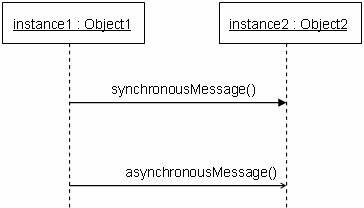
Figure 11: the Message
The message / method name is placed above the arroved line. The message that is being sent to the recieving object represents an operation / method that the recieving object's class implements. In figure 12, the analyst object makes a call to the system object which is an instance of the ReportingSystem class. The analyst object is calling the system object’s getAvailableReports method. The system object then calls the getSecurityClearance method with the argument of userId on the secSystem object, which is of the class type SecuritySystem. (Note: When reading this sequence diagram, assume that the analyst has already logged into the system.)
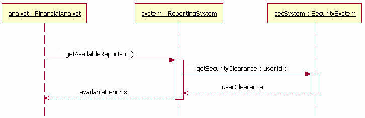
Figure 12: an example message, with return messages present
3.4. Guards#
When modeling object interactions, there will be times when a condition must be met for a message to be sent to the object. Guards are used throughout UML diagrams to control flow. In figure 14, the guard is the text "[pastDueBalance = 0]". By having the guard on this message, the addStudent message will only be sent if the accounts recievable system returns a past due balance of zero. The notation for this in UML is pretty simple.
[pastDueBalance = 0]
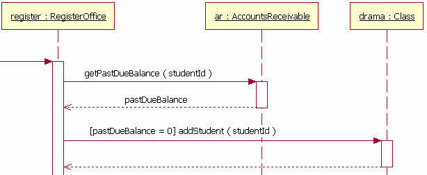
Figure 13: the Guard
3.5. Alternatives#
We use alternatives to designate a mutually exclusive choice between two or more message sequences. While it is possible for two or more guard conditions attached to different alternative operands to be true at the same time, but at most only one operand will actually occur at run time. Alternatives allow the modelling of the classic "if then else" logic we have come to know (and maybe even love).
An alternative combination fragment eleemnt is drawn using a frame. The word "alt" is placed inside the frame's namebox. The larger rectangle is then divided into what UML 2 calls operands. (Note: Although operands look a lot like lanes on a highway, I specifically did not call them lanes. Swim lanes are a UML notation used on activity diagrams.) Operands are separated by a dashed line. Each operand is given a guard to test against, and this guard is placed towards the top left section of the operand on top of a lifeline. (Note: Usually, the lifeline to which the guard is attached is the lifeline that owns the variable that is included in the guard expression.) If an operand’s guard equates to “true,” then that operand is the operand to follow.
Alternative combination fragments are not limited to simple "if then else" tests. There can be as many alternatives path as are needed (or as you want). If you need more alternatvies, then all you need to do is add an operand to the rectangle with that sequence's guard and messages.
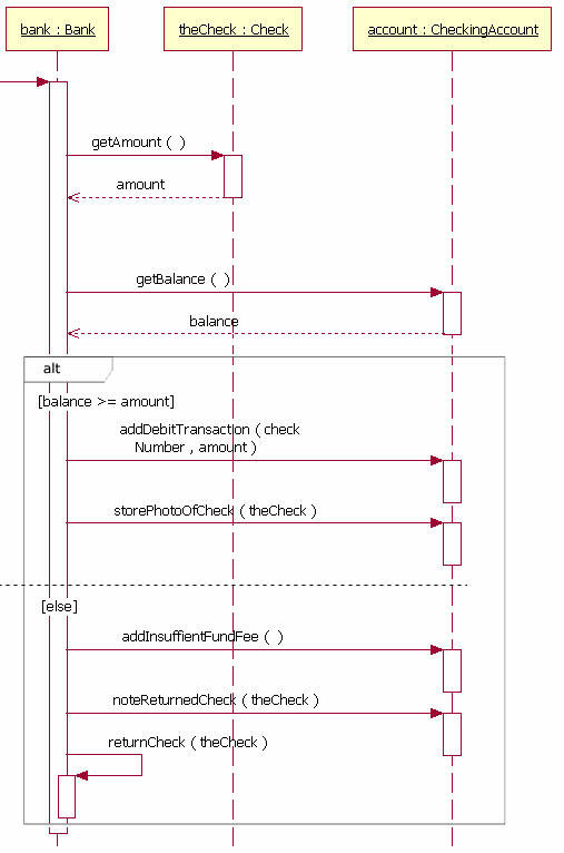
Figure 14: the Alternative
All information can be found in further detail at the References below.
4. References#
[1] Visual Paradigm: What is Sequence Diagram https://www.visual-paradigm.com/guide/uml-unified-modeling-language/what-is-sequence-diagram/
[2] The sequence diagram - IBM Developer https://developer.ibm.com/technologies/web-development/articles/the-sequence-diagram/