Entity Relationship Diagram - Level 5 #
1. Introduction#
Looking more at ERDs, this section will further discuss these types of diagrams, following up from the information provided at Level 4. If you are not sure on what the components of an Entity Relationship Diagram are, refer back to here.
2. Table of Contents#
3. Entity Notations and Attributes#
There are primarily four cases where you would want to use an Entity Relationship Diagram during design, which are;
- Database design
- Database debugging
- Database creation and patching
- Aid in requirmement gathering
ER Diagrams are composed of entities, relationships and attributes. They also depict cardinality, which defines relationships in terms of numbers. As we went through these in level 4, this time we are going to focus on hese with more detailed examples to help you shape your own work.
3.1. Entity#
Entities are defineable objects that can have some data stored about it. You should think about entities as nouns. The shape of an entity is typically shown as a rectangle.
3.2. Entity Attributes#
Also known as a column, an attribute is a property or characteristic of the entity that holds it. The attribute has a name that helps to describe the property and a type that describes the kind of attribute it is, such as varchar for a string, or int for an integer.

Figure 4: Example Entity with properties
3.3. Primary Key#
Sometimes known as PK, the primary key is a special kind of entity attribute that is used to uniquely define a record in a database table . For example, if we have a unique ID for each purchase in a database, but one of the transactions has the same ID as another transaction, and this transaction ID is our PK, then this is an error and shouldn't be possible, as our PK must always be unique. Lets look at a visual example of this:

Figure 5: Primary Key example
As we mentioned before, this type of ID cannot have a duplicate, so this would be an error that we would need to fix within the database.
3.4. Foreign Key#
Sometimes known as FK, the foreign key is a reference to a primary key in another table. It is used as a way to identify the relationships between entities. Note that foreign keys don't need to be unique, unlike primary keys. Multiple records can share the same values. The example below shows an entity with some columns, showing where a reference might take place.

Figure 6: Foreign Key example
3.5. ER Relationships#
Remember that relationships help to signify the connection between two entities that are associated with each other in some way.
3.6. ER Cardinality#
This is the definition that defines the numerical attributes between two entities or entity sets. Recall we we have the three main caridnal relationships of one-to-one, one-to-many and many-to-many.
- One-to-one: A one-to-one relationship is mostly used to split an entity in two to provide information concisely and make it more understandable, the example below shows this in practice:

- One-to-many: A one-to-many relationship refers to the relationship between two entities X and Y in which an instance of X may be linked to many instances of Y, but an instance of Y is only linked to one instance of X

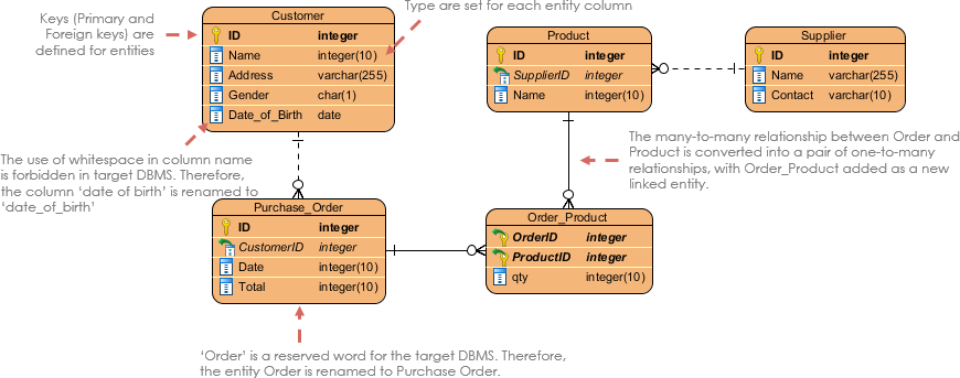
- Many-to-many: Many-to-many refers to the relationship between two entities X and Y in which X may be linked to many instances of Y and vice versa. Note that a many-to-many relationship is split into a pair of one-to-many relationships in a physical ERD.

3.7. Example ER Diagram#
The diagram below shows an example of a good, simple ER diagram showing the Physical Data Model. The Physical Data Model represents the actual design of a relational database. At Level 5, we are expecting you to create good quality ER diagrams, similar to the one below:

Figure 7: Physical Data Model example ER Diagram
4. References#
[1] Visual Paradigm What is Entity Relationship Diagram https://www.visual-paradigm.com/guide/data-modeling/what-is-entity-relationship-diagram/#:~:text=Entity%20Relationship%20Diagram%2C%20also%20known,inter%2Drelationships%20among%20these%20entities.